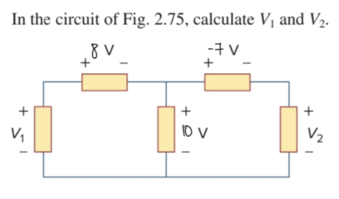
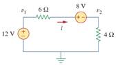
48+ in the circuit of fig. 2.75 calculate v1 and v2
V 1 V 4 IR 1. For the circuit shown in Fig find.
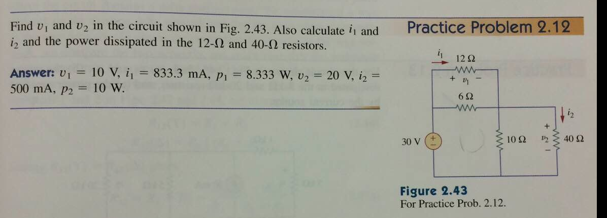
Solved Find V1 And V2 In The Circuit Shown In Fig 2 43 Chegg Com
Applying KVL on this circuit.
. Web In Figure 1 as 30 Ω and 375 Ω resistors are connected in parallel the equivalent resistance of parallel connected circuit is calculated as follows. Web Find v1 and v2 in the circuit shown in Fig Also calculate i1 and i2. Youll get a detailed.
Posted 3 months ago Q. TheEngineeringWei 278K subscribers Subscribe 26K views 2 years ago In the circuit of Fig. Web Q1 figure1 apply KVL in loop1 10-3Vo0 Vo -7volt apply KCL at node1 2 1Id Io 1amp apply KCL at node 2.
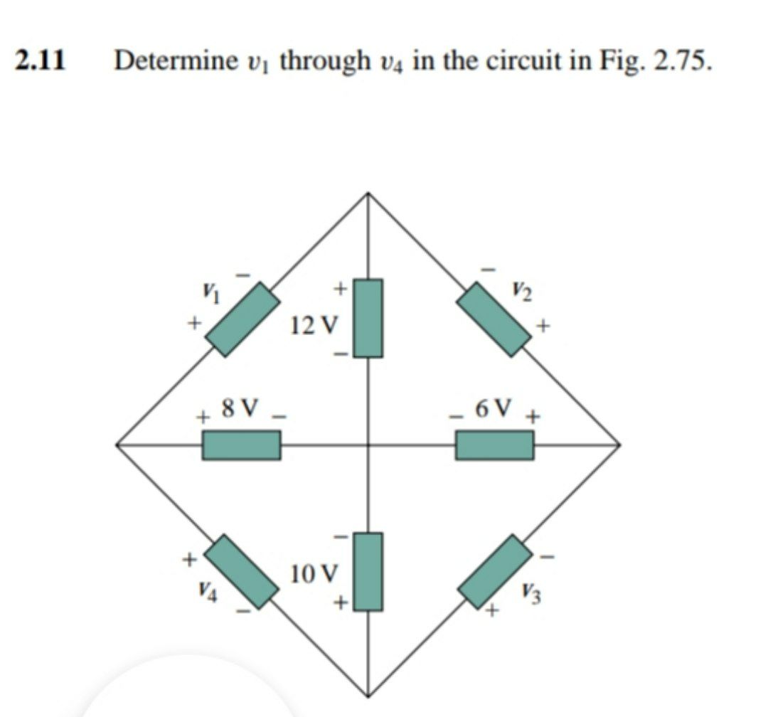
In the circuit of Fig. A v1 and v2 b the power dissipated in the 3-k and 20-k. 275 calculate V1 and V2.
275 calculate V1 and V2. Web In the circuit of Fig. 275 calculate V and V2.
8V -7 V. A v1 and v2 b the power dissipated in the 3-k and 20-k resistors. Web The sign of voltage drop across the passive element is such a way that the current entering from the positive terminal.
8 V -7 V V2 Question need asap Transcribed Image Text. 275 calculate V1 and V2. This problem has been solved.
211 In the circuit of Fig. 1 V 2 V V 5 V V2 Figure 275 For Prob. Web 211 In the circuit of Fig.
Web This is one way of checking resultsPractice Problem 213 For the circuit shown in Fig.
Fundamentals Of Electric Circuits Second Edition
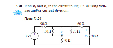
Solved Find V1 And V2 In The Circuit In Fig P3 30using Chegg Com
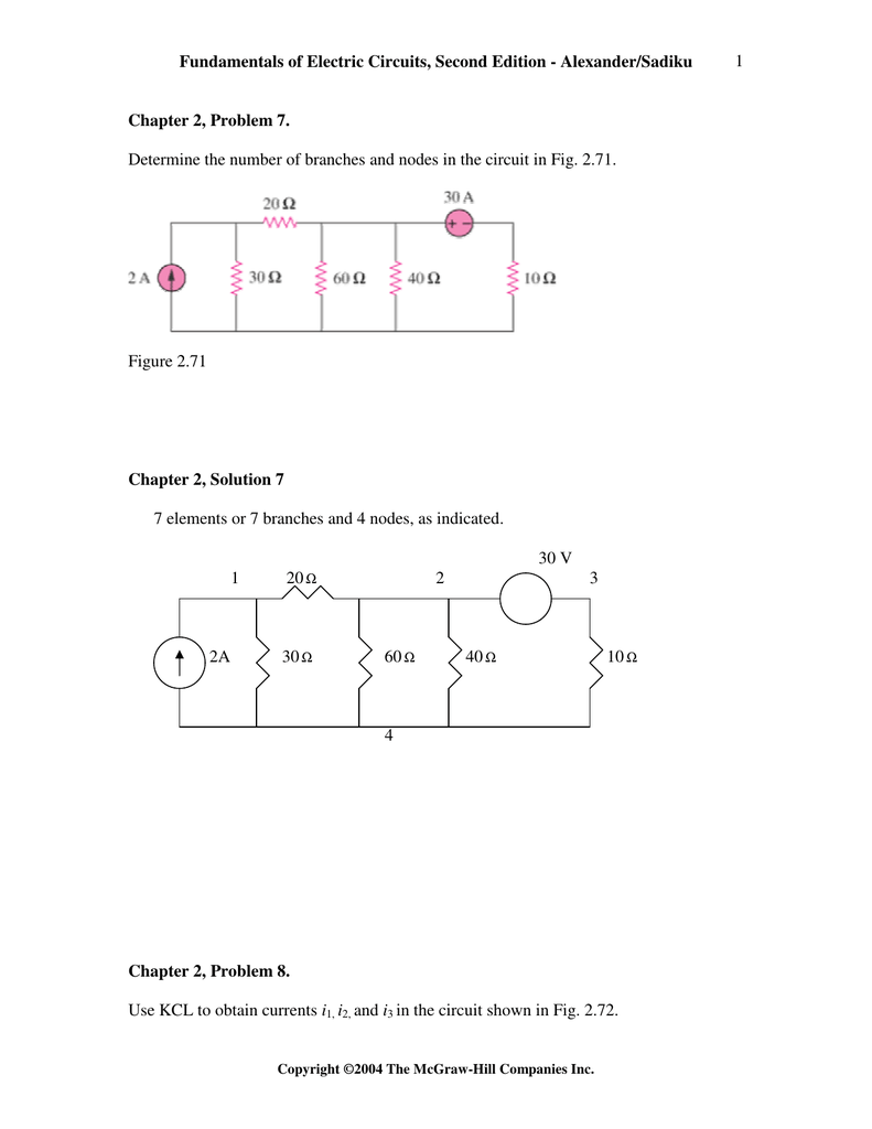
Fundamentals Of Electric Circuits Second Edition

Master Catalog 74 By Forestry Suppliers Issuu

Alexander 2 Fig Practice Prob Circuit Pubhtml5

Control System Engineering By Nagoor Kani First Edition Pdf Pdf
2 11 In The Circuit Of Fig 2 75 Calculate V1 And V2 Youtube
Solved I Don T Understand How To Deal With Large Circuits Of This Nature Course Hero

2 11 In The Circuit Of Fig 2 75 Calculate V1 And V2 Youtube
Solved In The Circuit Of Fig 3 47 The Voltage V 2 Is Figure 3 47 In 1 Answer Transtutors
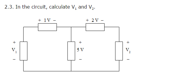
Solved 2 3 In The Circuit Calculate V1 And V2 Chegg Com

Control System Engineering By Nagoor Kani First Edition Pdf Pdf
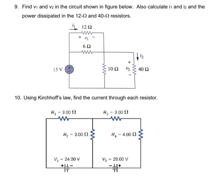
Solved 9 Find V1 And V2 In The Circuit Shown In Figure Chegg Com
Answered 2 11 Determine Vị Through V4 In The Bartleby
Fundamentals Of Electric Circuits Second Edition
1982 Ind502 Sprague Integrated Circuits 1982 Ind502 Sprague Integrated Circuits

Alexander 2 Fig Practice Prob Circuit Pubhtml5